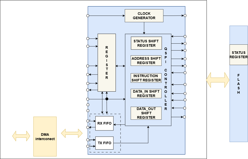
QSPI IP is a high-speed interface designed for fast and efficient communication with external flash memory. It uses four data lines (IO0-IO3) instead of one, enabling higher data transfer speeds. It supports Single, Dual, and Quad SPI modes, enabling up to four times faster data transfer than standard SPI

| Name | Width | Direction | Description |
|---|---|---|---|
| clk | 1 | Input | Global clock signal |
| rst_n | 1 | Input | Global reset signal |
| sclk_i | 1 | Input | Used as input for the clk in slave mode |
| cs_i | NUM SLAVES | Input | Used as input for chip select in slave mode |
| rx_i | 1 | Input | Used for serial data in |
| scan_mode | 1 | Input | Scan mode selection signal (DFT Signal) |
| scan_en | 1 | Input | Scan enable signal (DFT Signal) |
| cs_o | NUM SLAVES | Output | Used as output for chip select in master mode |
| sclk_o | 1 | Output | Used to output the clk in master mode |
| txd | 1 | Output | Used for serial data |
| Generic Bus Interface | 98 | Input/Output | Generic Bus Interface Signals. More details in the design document |
| DMA Interface | 137 | Input/Output | Generic DMA Interface Signals. More details in the design document |

| Name | Width | Direction | Description |
|---|---|---|---|
| clk | 1 | Input | Global clock signal |
| rst_n | 1 | Input | Global reset signal |
| sclk_i | 1 | Input | Used as input for the clk in slave mode |
| cs_i | NUM SLAVES | Input | Used as input for chip select in slave mode |
| rx_i | 1 | Input | Used for serial data in |
| scan_ mode | 1 | Input | Scan mode selection signal (DFT Signal) |
| scan_en | 1 | Input | Scan enable signal (DFT Signal) |
| cs_o | NUM SLAVES | Output | Used as output for chip select in master mode |
| sclk_o | 1 | Output | Used to output the clk in master mode |
| txd | 1 | Output | Used for serial data |
| Generic Bus Interface | 98 | Input/ Output | Generic Bus Interface Signals. More details in the design document |
| DMA Interface | 137 | Input/ Output | Generic DMA Interface Signals. More details in the design document |
Ready to discuss your IP Solutions needs? Contact us to schedule an appointment with one of our experts.
 by Digital GYB